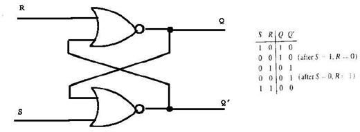
Circuit Diagram Of D Flip Flop
View Circuit Diagram Of D Flip Flop Gif. Whereas, d latch operates with enable signal. They can be used in toggle circuits.

Let us explore some which are listed below:
A method to solve combination of 3 or more 1(s) using state tables and the consequently applying principle of d flip flop hope this video was helpful. It contains two transistors, each transistor base is connected to others collector for get a feedback. So, a logic diagram can be developed on the basis of these relations as Due to its versatility they are available as ic packages.
0 Response to "Circuit Diagram Of D Flip Flop"
Post a Comment