26+ Circuit Diagram Of 4 1 Multiplexer Gif. Mux circuit block diagram is shown in fig. Design truth table,logical expression,circuit diagram for it.
LogicBlocks Experiment Guide - learn.sparkfun.com from cdn.sparkfun.com A multiplexer can take any number of inputs line but then the. The main function of the mux is that it combines i/p signals, permits the control bit ab decides which of the i/p data bit should transmit the output. Alibaba.com offers 1,196 electrical circuit diagrams products.
Multiplexer is a combinational logic circuit which allows only one input at a particular time to generate the output.
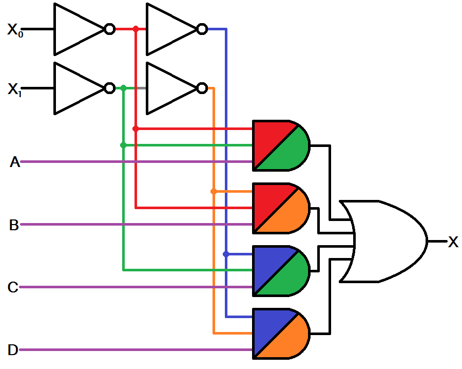
It uses a tree architecture with a recursive series of 2 : The truth table can easily be modified for muxes are most often used in digital circuits to transfer data elements from a memory array to data processing. We can easily understand the operation of the above circuit. The following figure shows the 4x1 multiplexer circuit diagram using and gates.
Share this post
0 Response to "Circuit Diagram Of 4 1 Multiplexer"

0 Response to "Circuit Diagram Of 4 1 Multiplexer"
Post a Comment