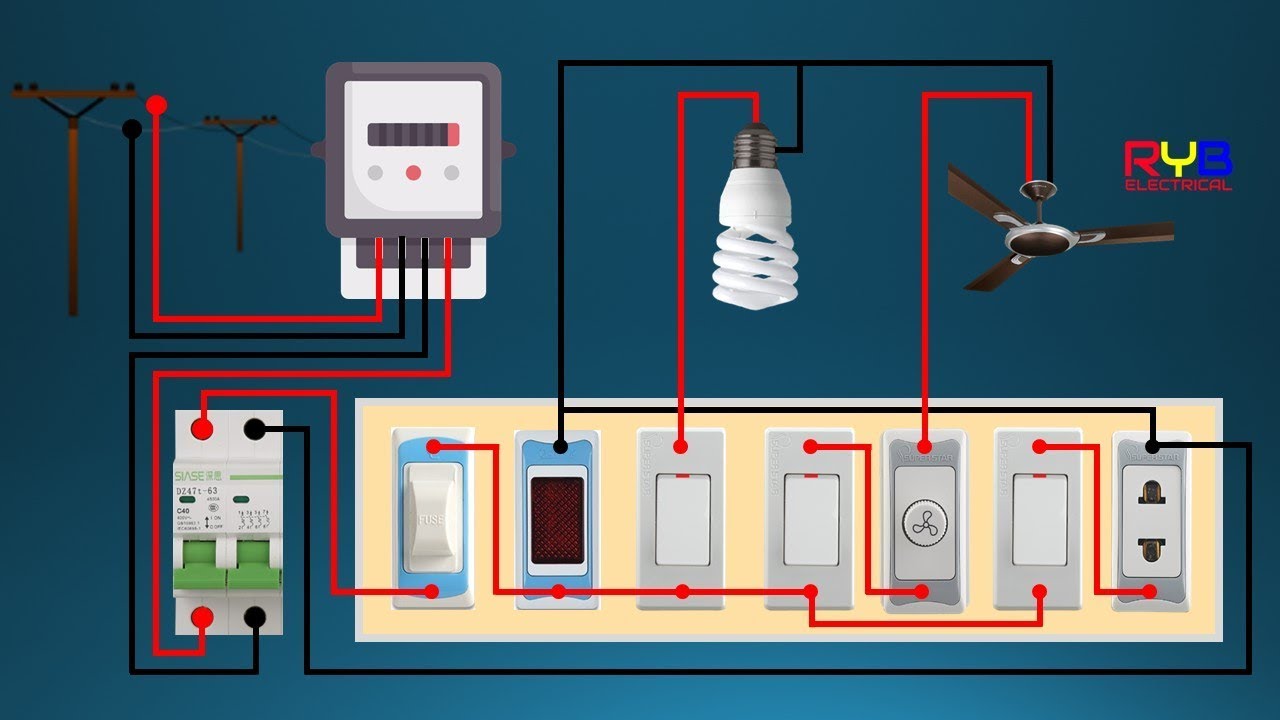
Basic Building Wiring Diagram
Get Basic Building Wiring Diagram Images. A wiring diagram is a simplified conventional pictorial representation of an electrical circuit. The basic home electrical wiring diagrams described above should have provided you with a good understanding.
A floor plan is a basic architectural diagram.
For example, the proper location of light fixtures and electrical outlets can all the bare copper or ground wires are now connected. The introduction of hazardous voltages into the low voltage circuits of the system (e.g. When troubleshooting a faulty ground point, checking the system circuits which use a common ground may. This article describes general aspects of electrical wiring as used to provide power in buildings and structures, commonly referred to as building wiring 1.

0 Response to "Basic Building Wiring Diagram"
Post a Comment