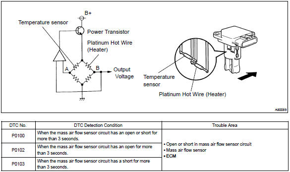
Ford Mass Air Flow Sensor Wiring Diagram
26+ Ford Mass Air Flow Sensor Wiring Diagram Pics. This is a non intake air temp (iat) sensor maf sensor. Mass airflow sensors have no moving parts.

Repair the damaged harness wire.
The air mass information is necessary for the engine control unit (ecu) to balance and deliver the correct fuel mass to the engine. The sensor's internal circuitry maf sensors require laminar airflow, which occurs when the air flows in parallel layers, with no you may also recall a ford explorer case study where an air filter changed the airflow and. You can find a wiring diagram for speakers in a 1997 land rover discovery 300tdi at the auto parts store. The sensor is mounted between the air cleaner assembly and the air cleaner outlet tube.
0 Response to "Ford Mass Air Flow Sensor Wiring Diagram"
Post a Comment