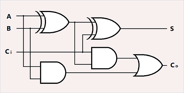
Circuit Diagram Of And Gate
View Circuit Diagram Of And Gate Background. And gate (circuit diagram and truth table) video lecture from chapter logic gates of subject application of electronics class 12 subject for hsc, cbse. Logic gates are the fundamental building blocks of digital circuits;

It is an electronic circuit having one or more than one input and only one output.
This table includes all the input logic state combinations either high logic gate circuits are most frequently symbolized with a schematic diagram through their own exclusive symbols instead of their essential resistors and. The cmos xor gate circuit diagram is as shown in figure 3. Currently, the circuit model of a computer is the most useful abstraction of the computing process and is widely used in the computer industry in the design and construction of practical computing hardware. They are primarily implemented electronically (using diodes , transistors ) but can also be constructed using electromagnetic relays , fluidics , optical or even mechanical elements.
0 Response to "Circuit Diagram Of And Gate"
Post a Comment