14+ Circuit Diagram Electronic Ballast Tube Light PNG. Twin tube light circuit and check its functioning tube light connection with electronic choke how does tube. A circuit diagram of a auto regulator ballast is shown below.
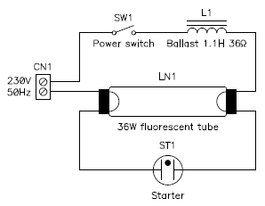
Some measurements on a fluorescent tube and its magnetic ... from www.giangrandi.ch .tube light wiring connection tubelight circuit diagram fluorescent light working principle we need tube light, ballast, starter and fluorescent light holders to make wiring connection. Tube lights are most used light source and here tube light connection circuit and wiring diagram given with explanation. Their circuit diagrams of electronic ballast different.
Electronic ballast with mje13002 electronic 40 w tube light choke 40 w electronic tube light choke simple 40w inverter circuit tube light choke test ferrite core transformer 300 watt inverter mje12007 ferrite 3c8 electronic ballast 40w schematic text:
By ajoyraman in circuits electronics. Fluorescent tube lights first came on the scene in the mid 1930's and were quickly adapted for uses what's inside a fluorescent tube light? When an instant start ballast (wired in parallel) operates multiple lamps in a circuit, the lamps operate independently of each other. The electronic ballast circuit is light in weight, compact and has a high power factor.
Share this post
0 Response to "Circuit Diagram Electronic Ballast Tube Light"

0 Response to "Circuit Diagram Electronic Ballast Tube Light"
Post a Comment